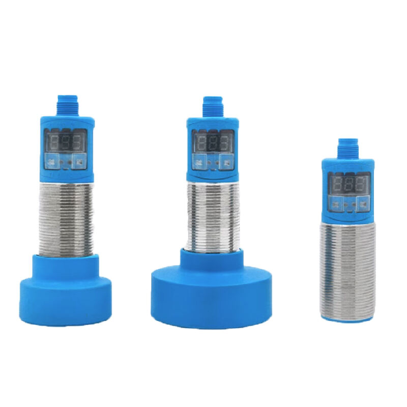
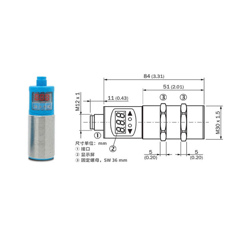
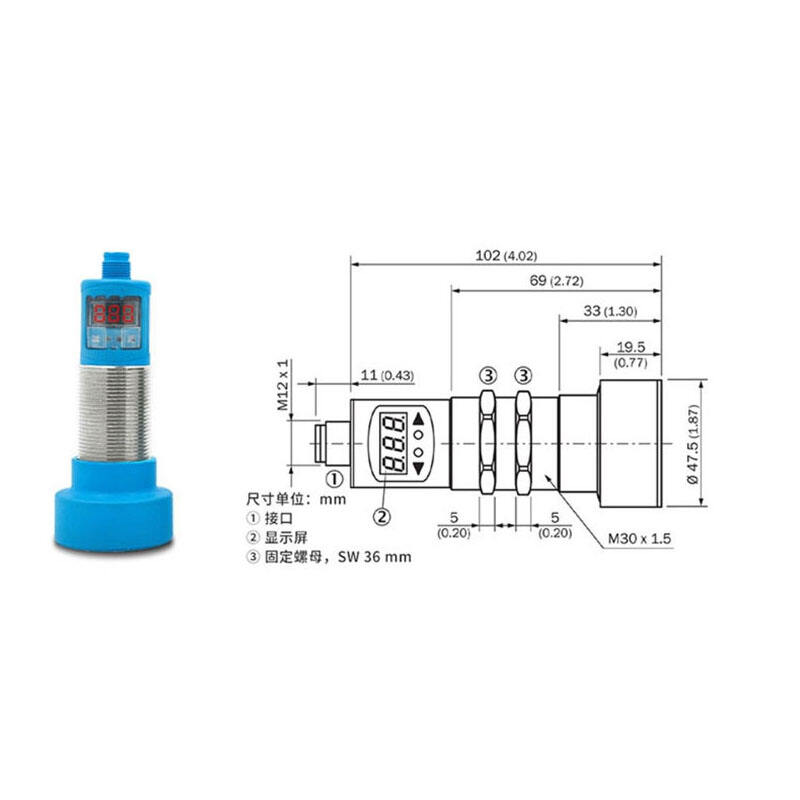
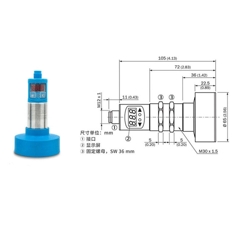
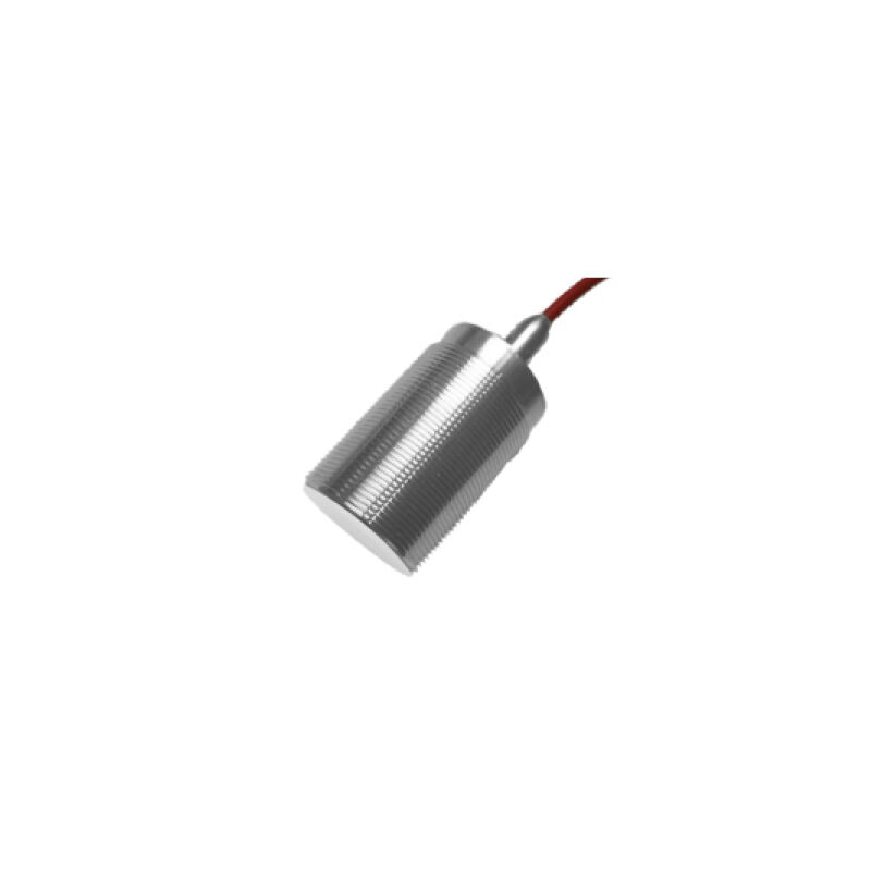
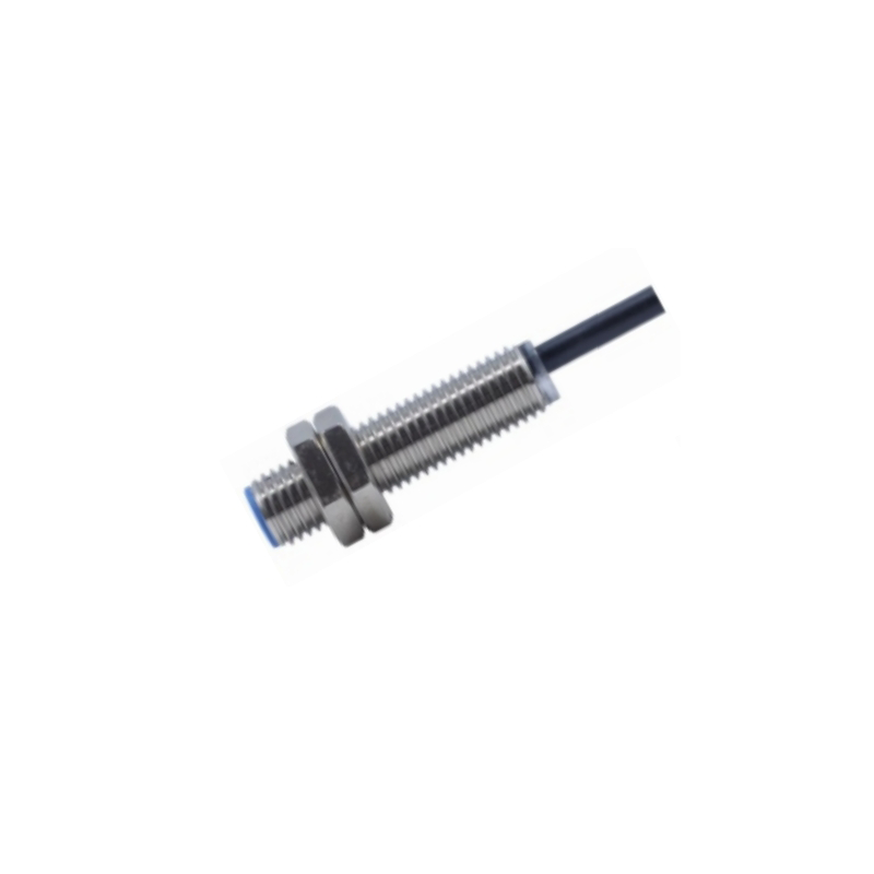
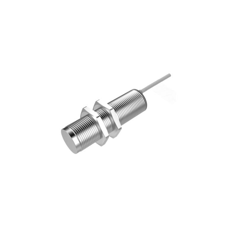
SN:2000mm Digital ultrasonic sensor
The principle of ultrasonic distance measurement is to emit sound waves through an ultrasonic transmitter, and when the sound waves encounter obstacles, they return. The distance between the transmitter and the obstacle is calculated based on the conduction velocity and return time of the sound waves. This is the time difference distance measurement method. Ultrasonic waves are also a type of sound wave, and their propagation speed is related to factors such as temperature and pressure, but the influence of temperature can be ignored when the temperature changes little. If there is a high requirement for distance measurement, temperature compensation should be used for calibration
- Overview
- Related Products
| Product model | UBX200-GM30-V4-H5 | UBX400-GM30-V4-H5 | UBX600-GM30-V4-H5 | UBX800-GM30-V4-H5 | |
| UBX200-GM30-V5-H5 | UBX400-GM30-V5-H5 | UBX600-GM30-V5-H5 | UBX800-GM30-V5-H5 | ||
| UBX200-GM30-V6-H5 | UBX400-GM30-V6-H5 | UBX600-GM30-V6-H5 | UBX800-GM30-V6-H5 | ||
| UBX200-GM30-V7-H5 | UBX400-GM30-V7-H5 | UBX600-GM30-V7-H5 | UBX800-GM30-V7-H5 | ||
| UBX200-GM30-VI-H5 | UBX400-GM30-VI-H5 | UBX600-GM30-VI-H5 | UBX800-GM30-VI-H5 | ||
| UBX200-GM30-VU-H5 | UBX400-GM30-VU-H5 | UBX600-GM30-VU-H5 | UBX800-GM30-VU-H5 | ||
| Detection range |
80 ... 2000 mm | 200 ... 4000 mm | 350 ... 6000 mm | 400 ... 8000 mm | |
| Non-detection zone |
0 ... 80 mm | 0 ... 200 mm | 0 ... 350 mm | 0 ... 400 mm | |
| Transducer frequency |
approx. 180 kHz | approx. 85 kHz | About 65KHz | About 65KHz | |
| response time | About 195 ms |
145 ms minimum 440 ms factory setting |
285 ms minimum 850 ms factory setting |
285 ms minimum 850 ms factory setting |
|
| Standard target version | max. 30 Hz | max. 13 Hz | max. 7 Hz | max. 7 Hz | |
| type of output | V4 :NPN normally open/normally closed V6:2 switch outputs PNP, NO/NC, VI:4-20mA | ||||
| V5:PNP normally open/normally closed V7:2 switch outputs NPN, NO/NC, VU:0-10V | |||||
| working voltage |
10-30V DC ripple 10% | ||||
| Rated working current |
200mA Passage/overload protection | 2 x 100 mA , short- circuit/overload protected |
|||
| Repetition accuracy of |
≤ 0.5% | ≤ 0.1% | |||
| Range adjustment |
Adjust the farthest and nearest range through the adjusting line | ||||
| Degree of protection |
IP65 | ||||
| Connection mode | Connector plug M12 x 1 , 5-pin/2m PVC cable | ||||
| LED yellow light | The yellow light of the switch status indicator flashes. The target is detected under the set status | ||||
| LED red light | The red light is always on: error Red light flashing: no target is detected in the set state |
||||

